
Battery series · Part 8 of 10
How to avoid sizing your batteries on the wrong quiescent current measurements
Many voice alarm systems check their loudspeaker lines in short bursts, and the battery current rises during each one. One meter reading can catch the low figure or the high one, and the battery gets sized on it.
Reviewed on

Glance at a lighthouse once and you will say it is dark, or that it is dazzling. Both are true for a moment. Neither tells a ship what the light does all night.
A voice alarm that checks its loudspeaker lines in pulses looks the same to a clamp meter. Catch it between the pulses and the current looks low. Catch it on one and it looks high.
A clamp meter shows whichever part of the cycle it catches
Catching is the right word. A voice alarm system supervises its own wiring. Some systems do it continuously, with a pilot tone or a DC bias on the line. Others interrogate the lines at intervals: for example, 5 seconds in every 30, which is the calculator's own example.
On those systems the current from the standby battery settles, rises for the length of the pulse, and settles again. The meter shows whichever of those it happens to catch, and nothing on its display says which.
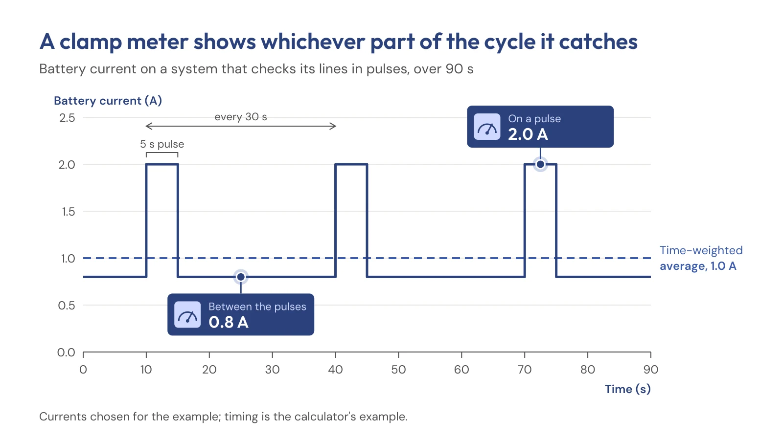
A reading is better than a guess, if it is the right reading. On a pulsing system, one reading is a sample of a cycle.
The idle current is carried for 48 times as long as the alarm current
That sample would matter less if the idle current were a small part of the battery. It is the largest part. The battery is sized for 24 hours of standby, then at least 30 minutes of evacuation messages in every alarm zone (BS 5839-8:2023, Clause 25.3.5 a). That is 24 hours against half an hour, so the battery carries the idle current for 48 times as long as the alarm current.
A small error in the idle figure therefore becomes a large error in the battery. A 1200 W voice alarm's battery is sized by its quietest 24 hours ran one system through the calculation: every extra 0.1 A of standby current cost about 3 Ah of battery.
The code expects the idle figure to cover the whole cycle. A note to the battery equation, guidance rather than a requirement, describes the standby current as the average of the quiescent currents of every part of the system, including the current taken by the fault monitoring circuits (Annex C, C.1.1). A sample of one moment is not that average, and the battery carries the difference for all 24 hours.
Two readings and a stopwatch give the figure the battery needs
To get that average, take two readings, not one. With the mains isolated and the reading settled, note the current between interrogations. Then note it during one. Time the pulse. Then time the period, from the start of one pulse to the start of the next.
The figure to use is the time-weighted average:
I₁ = I_between + (I_during − I_between) × pulse ÷ period
That is the formula in the calculator's monitoring tip. Enter your four figures in the quiescent current calculator and it does the sum for you. Or, at Level 2 of the Battery Calculator, you can skip the sum. Enter the between-pulse current as the quiescent current. Set the monitoring to "Intermittent (cycle known)", and enter the rise during the pulse as the "Increase during an interrogation", with the pulse and the period. The answer is identical.
The supervised figure can be several times the sleeping figure
That answer assumes the current pulses. Not every system does. Where the monitoring is continuous, the current does not rise and fall, and one settled reading is the figure. What you are reading then is the supervised current: the system with its line monitoring running.
Some manufacturers print two figures, one with the monitoring running and one without. Where both are printed, the supervised figure can be several times the sleeping figure beside it. The sleeping figure is the smaller and more tempting one. It is the wrong one for the battery, because the monitoring runs for all 24 hours.
Two traps follow. If you take the supervised figure from a datasheet, leave the calculator's monitoring current at 0. That figure already includes the monitoring, and entering it again oversizes the battery. And if the pulses on an interrogating system are too short for your clamp meter to resolve, no reading will catch them reliably. Use the manufacturer's figure instead.
One system, three readings, three different batteries
Where the meter can catch the pulses, here is what the choice of reading does. Take the same 1200 W system: Class D amplifiers, a 24 V battery, speech messages, and Level 2 of the calculator with no battery chosen. Suppose the meter settles at 0.8 A between interrogations and rises to 2.0 A during them, 5 seconds in every 30. Those currents are chosen for the example; the timing is the calculator's example.
| Quiescent current entered | Minimum capacity | Next size in the calculator's range |
|---|---|---|
| 0.8 A, read between the pulses | 35.36 Ah | 38 Ah |
| 2.0 A, read during a pulse | 73.09 Ah | none: above the largest, 65 Ah |
| 1.0 A, the time-weighted average | 41.65 Ah | 65 Ah |
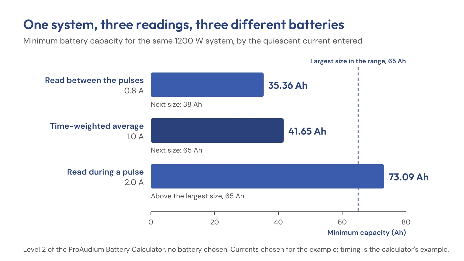
Read between the pulses, the answer comes out 15 % low. It points at a 38 Ah battery where the system needs 41.65 Ah. Read on a pulse, it comes out 75 % high, beyond any single block in the range. The right answer sits between the two readings, and so does the right battery.
Make the pulse taller, 3.2 A instead of 2.0 A, and both errors grow: 26 % low between the pulses, 131 % high during one.
Write both readings and the timing on the record
Neither error shows up later unless the record shows how the figure was taken. Put both readings on the measurement record, with the pulse and the period beside them. Then the next person can check the sum rather than take the result on trust. A record that gives one current and no timing can't say which part of the cycle it caught.
"There's a quiescent figure on the report every year"
Then it is worth one question: is it one reading or two, and is the timing written beside it? If the system's monitoring pulses, that line is the difference between a figure and a sample.
In short
- On a system that checks its lines in pulses, one clamp reading lands between the pulses or on one.
- Between, it reads low; on a pulse, it reads high. In the example, that sizes the battery 15 % low or 75 % high.
- The battery needs the time-weighted average of two readings, and the calculator's Level 2 fields do the sum.
- Ask for both readings and the timing on the record.
A lighthouse is judged over the night, not at a glance. So is the current a voice alarm draws over 24 hours.
Next step. On the next service report, ask for the quiescent current as two readings with the pulse timing beside them, or for a note that the monitoring is continuous. Where a quiescent reading is already taken with the mains off, the second reading and the timing come from the same visit. To see what the figure does to the battery, open the three examples above and change them to your own system's figures at Level 2 of the ProAudium Battery Calculator. No email, no form. If you would like the calculation checked against what is installed, contactus@proaudium.com or 01273 034630.
Where this comes from
Every requirement this page relies on, with its clause, our explanation in our own words, and the official source to check it against. We paraphrase the standards; we do not reproduce their text.
| What the article says | Source | In our words | Official source |
|---|---|---|---|
| 24 h standby, then at least 30 min of evacuation messages in all alarm zones | BS 5839-8:2023, Clause 25.3.5 a) | Our explanation | BSI: BS 5839-8 |
| The standby current is described as the average of the quiescent currents of all the system's components, including fault monitoring (a note: guidance) | Annex C, C.1.1, Note to I1 | Our explanation | BSI: BS 5839-8 |
| Every extra 0.1 A of standby current costs about 3 Ah on a 1200 W, eight-zone system | Published part 6, ProAudium Battery Calculator Level 1 engine | A 1200 W voice alarm's battery is sized by its quietest 24 hours | Not applicable |
| Monitoring is continuous or periodic, for example 5 s in every 30; measure between and during, take the time-weighted average; use the manufacturer's figure if the pulse is too short to resolve; a supervised figure already includes monitoring | ProAudium Battery Calculator, monitoring and quiescent-current field tips | Battery Calculator | Not applicable |
| Where a manufacturer prints both, the supervised figure can be several times the sleeping figure printed beside it | ProAudium Battery Calculator, quiescent-current tip | Battery Calculator | Not applicable |
| All capacities in the example table | ProAudium Battery Calculator, Level 2, no battery chosen, run 20 October 2026 with the calculator's own engine; each row links its inputs | Battery Calculator | Not applicable |